- Clevises
- Overview
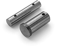
- Pins
- Specifying and Ordering Clevises
 |
||||||||||||||||||||||||||||||||||||||||||||||||||||||||||||||||||||||||||||||||||||||||||||||||||||||||||||||||||||||||||||||||||||||||||||||||||||||||||||||||||||||||||||||||||||||||||||||||||||||||||||||||||||||||||||||||||||||||||||||||||||||||||||||||||||||||||||||||||||||||||||||||||||||||||||||||||||||||||||||||||||||||||||||||||||||||||||||||||||||||||||||||||||||||||||||||||||||||||||||||||||||||||||||||||
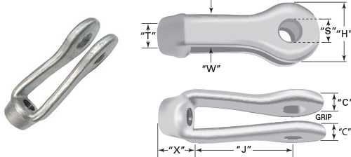
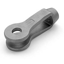
Clevises are used to connect tie rods and hanger assemblies to structural steel or fabricated lugs. The pin connection ensures that the rod is loaded only in tension and sees no bending forces. Our clevises are widely used in structural steel bracing and pipe support applications. Length adjustment of rod assemblies can be provided by pairing RH and LH threaded clevises with single lengths of rod or by using RH threads on both clevises with two rods and a turnbuckle or sleeve nut. |
||||||||||||||||||||||||||||||||||||||||||||||||||||||||||||||||||||||||||||||||||||||||||||||||||||||||||||||||||||||||||||||||||||||||||||||||||||||||||||||||||||||||||||||||||||||||||||||||||||||||||||||||||||||||||||||||||||||||||||||||||||||||||||||||||||||||||||||||||||||||||||||||||||||||||||||||||||||||||||||||||||||||||||||||||||||||||||||||||||||||||||||||||||||||||||||||||||||||||||||||||||||||||||||||||
|
Notes Regarding Strength The AISC safe working load listed in Clevis Table 1 is based on the net tensile area through the maximum pin hole, 60,000 Psi ultimate tensile strength material and a 5:1 safety factor. The allowable pin and tap size combinations in Clevis Table 2 are based on maintaining a net tensile stress area though the pin hole at 125% of the UNC tensile stress area of the rod. All of the pin diameters shown in Clevis Table 2 will likewise exceed the corresponding rod strength based on shear, but they should be investigated for bending if large grips are used (greater than 1-1/2") and there is a significant difference between the material thickness and the grip size (greater than 1/2"). The threaded area of carbon steel clevises forged to ASTM A668 Class A is equivalent to an ASTM A563 Grade C heavy hex nut. For high-strength applications, our carbon steel clevises can be heat treated up through ASTM A668 Class 'F'. |
||||||||||||||||||||||||||||||||||||||||||||||||||||||||||||||||||||||||||||||||||||||||||||||||||||||||||||||||||||||||||||||||||||||||||||||||||||||||||||||||||||||||||||||||||||||||||||||||||||||||||||||||||||||||||||||||||||||||||||||||||||||||||||||||||||||||||||||||||||||||||||||||||||||||||||||||||||||||||||||||||||||||||||||||||||||||||||||||||||||||||||||||||||||||||||||||||||||||||||||||||||||||||||||||||
Applications
Clevises are used to connect the rods and hanger assemblies to structural steel of fabricated lugs. The pin connection ensures that the rod is loaded only in tension and sees no bending forces. Our clevises are widely used in structural steel bracing and pipe support applications.
Length adjustment of rod assemblies can be provided by paring RH and LH threaded clevises with single lengths of rod or by using RH threads on both clevises with two rods and a turnbuckle or sleeve nut.
Relevant Standards
Clevises are manufactured to meet the dimensions and load ratings shown in the American Institute of Steel Construction Inc. (AISC) Steel Construction Manual, 13th edition, pages 15-14 and 15-15. Carbon and alloy steel clevises are forged per ASTM A668. Stainless clevises are forged per ASTM A473.
Materials
Clevis forgings are available in C1035 steel, ASTM A668 Class A, and 316 stainless steel, ASTM A473 Designation A. Heat-treated carbon and alloy steel clevises are available by special order.
Finishes
Standard finish for carbon steel clevises is plain steel, shot blasted after forging. Hot dip galvanizing is available as well as zinc electroplating. Standard processing for stainless steel clevises after forging is pickling and passivation. An electro-polished finish is also available for stainless steel parts.
Threads
Standard threads are UNC 2B, with the UNF thread series and metric M profile also available. We can also provide clevises with pipe threads for non-structural applications. Hot dip galvanized clevises are normally tapped oversize after galvanizing to accommodated the zinc coating on the rod threads.
 |
|
Pins Standard pin material is carbon steel with 50 Ksi minimum yield strength. Pins are available in headed or straight configurations. Steel clevises are supplies with headed pins up to 1" in dia. and straight pins from 1 1/8" dia. and up.
|
|
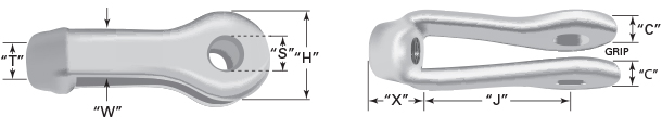
Specifying and Ordering Clevises • Determine clevis number based on safe working load and rod size using Clevis Table 1. Your application's maximum load should be less than or equal to value shown in 'Safe Working Load' column, and your rod size should be less than or equal to number shown in 'Maximum Tap Size' column. If not, select a larger size clevis. • Select pin diameter using Clevis Table 2 by locating your rod (tap) size in the first column, then moving across that row to find your clevis size. The allowable pin diameters are listed at the top of each column where your clevis number appears. • Determine grip size based on the thickness of the material that will receive the pin. The grip size is normally specified as material thickness + 1/4", however the minimum grip for #2 through #3 clevises is 3/4", #3-1/2 is 7/8" and 1" for #4 through #7 clevises. Grip dimensions are normally called out in 1/4" increments. • Specify the desired finish (typically plain or HDG) and any other special requirements.
|
|||||||||||||||||||||||||||||||||||||||||||||||||||||||||||||||||||||||||||||||||||||||||||||||||||||||||||||||||||||||||||||||||||||||||||||||||||||||||||||||||||||||||||||||||||||||||||||||||||||||||||||||||||||||||||||||||||||||||||||||||||||||||||||||||||||||||||||||||||||||||||||||||||||||||||||||||||||||||||||||||||||||||||||||||||||||||||||||||||||||||||||||||||||||||||||||||||||||||||||||||||||||||||||||||||